Point source
Point sources are used for sound sources that can be approximated by a single small point.
Overview
Each Vehicle can contain any number of Point source objects, which include properties for their location, sound power and directivity.
Each of the Point sources are assigned a Point source library item, and in this way many Point sources can be reused across your project. Point sources can be added or deleted, by right-clicking on the appropriate items in the model objects view . The order of the Point sources in the model objects view is determined by their distance from the front of the Vehicle.
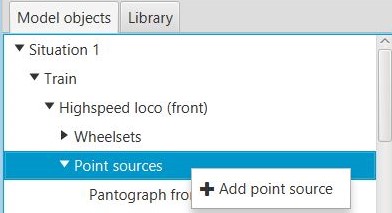
Right-click options for the 'Point sources' model object.
Input Parameters
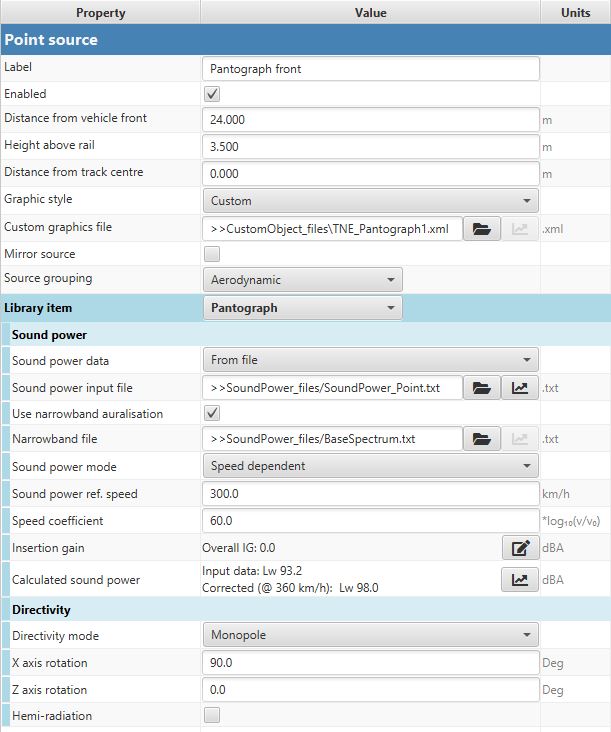
Properties for the 'Point source' model object.
| Name | Data type | Unit | Comment |
|---|---|---|---|
| Label | Text | - | A label for this Point source. This will be used to identify the point source in the calculation and results. Special characters are not allowed. |
| Enabled | Checkbox | - | Specifies whether this source is enabled in the calculation. This is a convenient method to deactivate a single source without removing it from the model. Note that for a source to be active in the calculations, its source grouping conditions must also be met. |
| Distance from front | Number | m | The distance between the front of the Vehicle and the Point source. |
| Height above rail | Number | m | The vertical distance between the top of the rail and the Point source. |
| Distance from track centre | Number | m | The horizontal distance between the centre of the track and the Point source. Positive values are towards the left from the perspective of a forward travelling train. |
| Graphic style | Choice | - | Select the graphic representation of this source, (for more info see below). This has no effect on calculations. |
| Custom graphics file | File | - | If the ‘Custom’ graphic style is selected, the file to use is specified here (with ’.xml’ file extension ). |
| Mirror source | Checkbox | - | Select to create a mirror image of this source, reflected in the xz plane. Directivities and positions will be mirrored (see 3D view for visual representation). |
| Source grouping | Lib. item | - | The Source group that this Point source belongs to. |
| Library item | Lib. item | - | The library item for the Point source. |
| Sound power data | Choice | - | Select what kind of method to use as the source data input, for example specified from a file, or a predefined source type e.g. motor, compressor. (For more info see below) |
| Use narrowband auralisation | Checkbox | - | Select to use a narrowband file for auralisation. This will take the narrowband data and shape it to fit the output 1⁄3 octave band results, applying Doppler shifts as necessary, and maintaining any tonal content. |
| Narrowband file | File | - | If the option to use narrowband data for the auralisation was selected, this is the file to be used for the narrowband spectrum (with ’.txt’ file extension ). |
| Sound power input file | File | - | * If the sound power data source has been selected as being ‘From file’, this is the file location for the Point source sound power (with ’.txt’ file extension ).* |
| Electrical power | Number | W | If the sound power data source has been selected as being ‘Motor’, this is the electrical power used for estimating the sound power level. |
| Sound power mode | Choice | - | Select whether the specified sound power is to be considered as ‘constant’ or ‘speed dependent’. |
| Input file speed | Number | km/h | If the sound power has been selected as being ‘speed dependent’, this is the reference speed used for the specified sound power level. |
| Speed coefficient | Number | - | If the sound power has been selected as being ‘speed dependent’, this is the speed coeefficient that will be used to apply a correction for the speed. For example, setting this to 30.0 will apply a 30.0 log10(v/v0) correction (where v and v0 are the train speed and reference input file speeds, respectively). |
| Insertion gain | - | - | Here, manual corrections can be specified to increase or decrease the sound power level data used in the calculations. Clicking on the button will launch a dialog window to input this data as either a single value for all frequencies, or as a pasted spectrum of corrections (comma separated over the range 20-20,000 Hz). Corrections can also be adjusted for individual frequency bands. |
| Calculated sound power | - | - | This shows the sound power levels that will ultimately be used in the calculation, taking into account any speed corrections and/or insertion gain specified. Clicking on the button will provide a plot and table of the values. |
| Directivity mode | Choice | - | Select whether the Point source directivity is monopole, dipole, a combined monopole/dipole, or specified from a file. |
| Monopole/dipole ratio | Number | 0-1 | If ‘combined monopole/dipole’ is selected as the directivity mode, this sets the proportion of monopole or dipole characteristic. 1 is fully monopole; 0 is fully dipole. |
| Dipole x axis rotation | Number | Deg | The rotation of the dipole directivity pattern about the x axis (the longitudinal axis of the track). |
| Dipole z axis rotation | Number | Deg | The rotation of the dipole directivity pattern about the z axis (the vertical axis). |
| User-defined directivity file | File | - | If ‘user-defined’ is selected as the directivity mode, the file location for the Point source directivity is specified here (with ’.txt’ file extension ). |
| Hemi-radiation | Checkbox | - | If hemi-radiation is enabled, then radiation is only considered for one side of this source. The side assumed to radiate is the left hand side from the perspective of a forward-travelling train (before any directivity rotation). In order to maintain sound power level consistency, the left hand side directivity is doubled (i.e. +3dB) to compensate. |
Graphic Styles
The following graphic styles for point sources are offered in Train Noise Expert:
| Name | Example image | Description |
|---|---|---|
| Point | 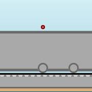 |
A simple point that shows the location of the Point source exactly as used in any calculations. |
| Pantograph 1 | 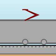 |
A simple pantograph graphic, by default positioned at roof level. |
| Pantograph 1 rev |  |
Pantograph 1 in the reverse direction. |
| Handrail 1 |  |
A simple vertical handrail, by default positioned at the centre of the modelled point source location. |
Sound power data sources
Train Noise Expert provides the following options for the sound power data source:
| Name | Description |
|---|---|
| From file | The sound power data is supplied from a File. |
| White noise | Values are provided in 1⁄3 octaves from 20-20,000 Hz, increasing by 3dB per octave. |
| Pink noise | Values are provided that are uniform in 1⁄3 octaves from 20-20,000 Hz. |
| Compressor | General values of compressor sound power levels have been taken from “Engineering Noise Control” by Bies, Hansen & Howard (5th Edition, Page 572), with values converted to 1⁄3 octave bands. Available types are:
|
| Motor | General values of large electric motor sound power levels have been taken from “Engineering Noise Control” by Bies, Hansen & Howard (5th Edition, Page 598), with values converted to 1⁄3 octave bands. Available types are:
|